MIL-PRF-25675C
4.6.14 Vibration. The valve shall be attached to a fixture capable of transmitting vibration. With the temperature of
the test fluid at 95° ± 15°F, the valve shall be flow-cycled at 3,000 psi and the rated flow. While the valve is being
cycled in this manner, it shall be vibrated as described in 4.6.14.1 and 4.6.14.2. All vibration measurements shall be
taken at the valve. Following the vibration test, the valve shall be subjected to the test indicated in 4.6.4. This
procedure shall be repeated for all three axes.
4.6.14.1
Resonance. Resonance shall be surveyed for 30 minutes, while the frequency of vibration is varied from 5
to 2,000 Hz, with one pass consuming 10 to 15 minutes (see Table III). This step shall be performed three times for
each axis.
TABLE III. Vibration data
Frequency (Hz)
Displacement in double amplitude (inch) and
Acceleration (g), if applicable
5-10
0.02
0.02 to 0.05 at ±1g
10-20
20-90
0.05
0.050 to 0.0001 at ±20g
90-2,000
4.6.14.2
Cycling. The valve shall be vibrated at resonant frequencies found in 4.6.14.1 and at the levels described
in Table III for 100 minutes. After 50 minutes, the frequency shall be increased to 110% of the resonant frequency
and flow-cycling shall be interrupted with pressure applied in the direction of checked flow (at the valve outlet). The
valve then shall be tested as specified in 4.6.5. The frequency then shall be reduced to 90% of the resonant frequency
with the flow-cycling interrupted and pressure applied in the direction of checked flow (at the valve outlet). Without
changing the valve position, the valve again shall be tested as specified in 4.6.5. Flow cycling shall be resumed,
resonant frequency returned, and the 100-minute vibration cycle completed.
4.6.15 Flexural strength. The valve shall be installed in a test setup similar to that shown in Figure 3. The test
setup shall be capable of vibration with a pressure of 3,000 psi applied to the inlet and outlet side of the valve. The
valve shall be vibrated at a frequency between 30 and 500 Hz for 10,000,000 cycles. The total stress level, which shall
consist of the tensile bending stress plus the axial tension due to the working pressure, shall be 20,000 (+0, -10%) psi.
This test shall be conducted with the hydraulic fluid temperature at 450° ± 10°F. Strain gages shall be placed 180°
apart, on the periphery of the mounting tubes. Any mechanical failure of parts or leakage due to this test shall be
cause for rejection. The test in 4.6.3 shall be performed at the conclusion of this test.
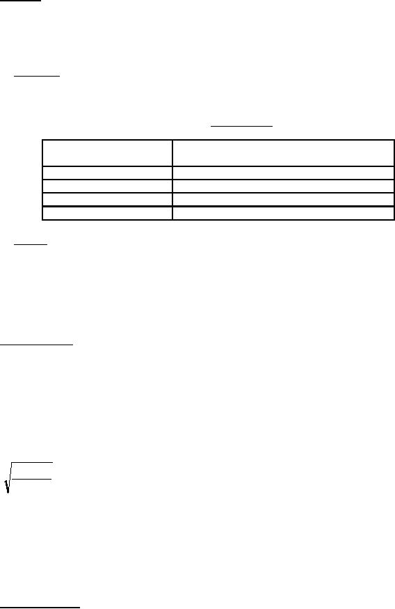
The length, L, shall be determined using the following equation:
12DEC
L=
(1)
S
where
L = total length (inches)
D = displacement due to vibration at the center of the check valve (inches)
E = modulus of elasticity (use 30,000,000 psi for corrosion-resistant steel)
C = one half of the tube outside diameter (inches)
S = stress in the tube at the strain gage (use 20,000 psi (+0, -10%) for corrosion-resistant steel)
4.6.16 Repeated assembly. A tube, sleeve, and nut (flared or flareless) shall be assembled to each end of the valve
and disassembled eight successive times using the torque specified in Table IV. The valve then shall be subjected to
the test indicated in 4.6.2.
7
For Parts Inquires call Parts Hangar, Inc (727) 493-0744
© Copyright 2015 Integrated Publishing, Inc.
A Service Disabled Veteran Owned Small Business